
Reverse Engineering the Guitar Hero 5 Neck Communication Protocol
The Guitar Hero 5 / Band Hero guitars use a 4-pin I2C connection between the guitar neck and body. In order to build an Arduino-based guitar for Clone Hero (using sanjay900’s great Ardwiino library), I reverse engineered the I2C communication. You can find the final code here.
This code will:
- Run on an Arduino (I used a low-power Pro Mini, but others will work)
- Communicate with the GH5 neck over I2C
- Activate a digital out when a neck button is pressed, to communicate with an Arduino running Sanjay900’s Ardwiino software
Worklog
2022-04-05
I open up the guitar to find that the neck connection on this one is 4 pins, unlike the previous guitar I’ve worked with which had 6 pins (5 buttons + ground). The previous guitar was an easy conversion: each button gets a digital input on the Arduino.
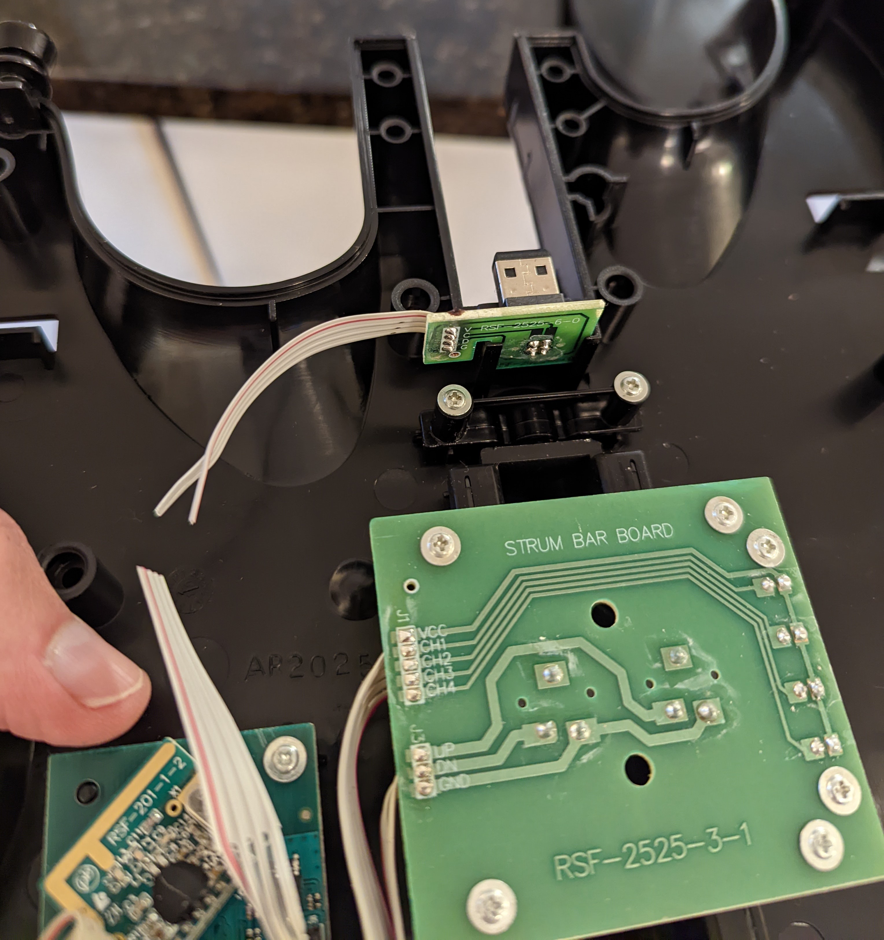
However, this guitar has pins labelled V, C, D, G. I2C is a common protocol with this number of lines: Vcc, SCL, SDA, and Ground. I attached my Saleae logic analyzer to the lines and powered up the guitar, hoping to sniff the communication, but all that happens is that the lines were driven high. I suspect I need to pair the controller to a receiver to get the microcontroller to activate the buttons, but I don’t have the receiver (or the Playstation2 Console for the receiver). Time to get more creative.
First, let’s check what voltage the guitar runs at. I plug in some batteries and poke at some of the VCCs internally to find they’re 3.3V.
I get my Sparkfun Qwiic Pro Micro and set it up. The hardware I2C is hard to access on this board, so I use a software I2C library and run the sample code to detect I2C devices.
Hoorah! I find that the peripheral is on address 0xD! However, trying to actually read from it only gets me 0xFF in reply… Time to get a dongle and sniff the real controller, I guess.
2022-04-12
The dongle ($100 on Ebay) has arrived. I toy with the idea of just using the dongle, but each dongle only pairs to one guitar at a time, and I have two guitars.
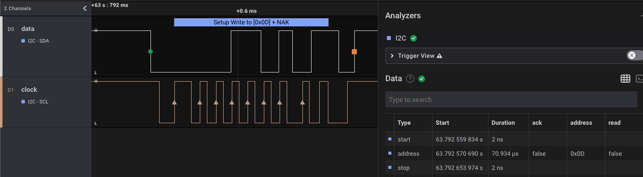
I plug the dongle in and pair the guitar to it, and use the logic analyzer to read the lines – and there’s activity! The microcontroller in the guitar is attempting to write to 0xD. So I had the address right, but I was trying to read from it, and clearly there’s some kind of handshake sequence necessary.
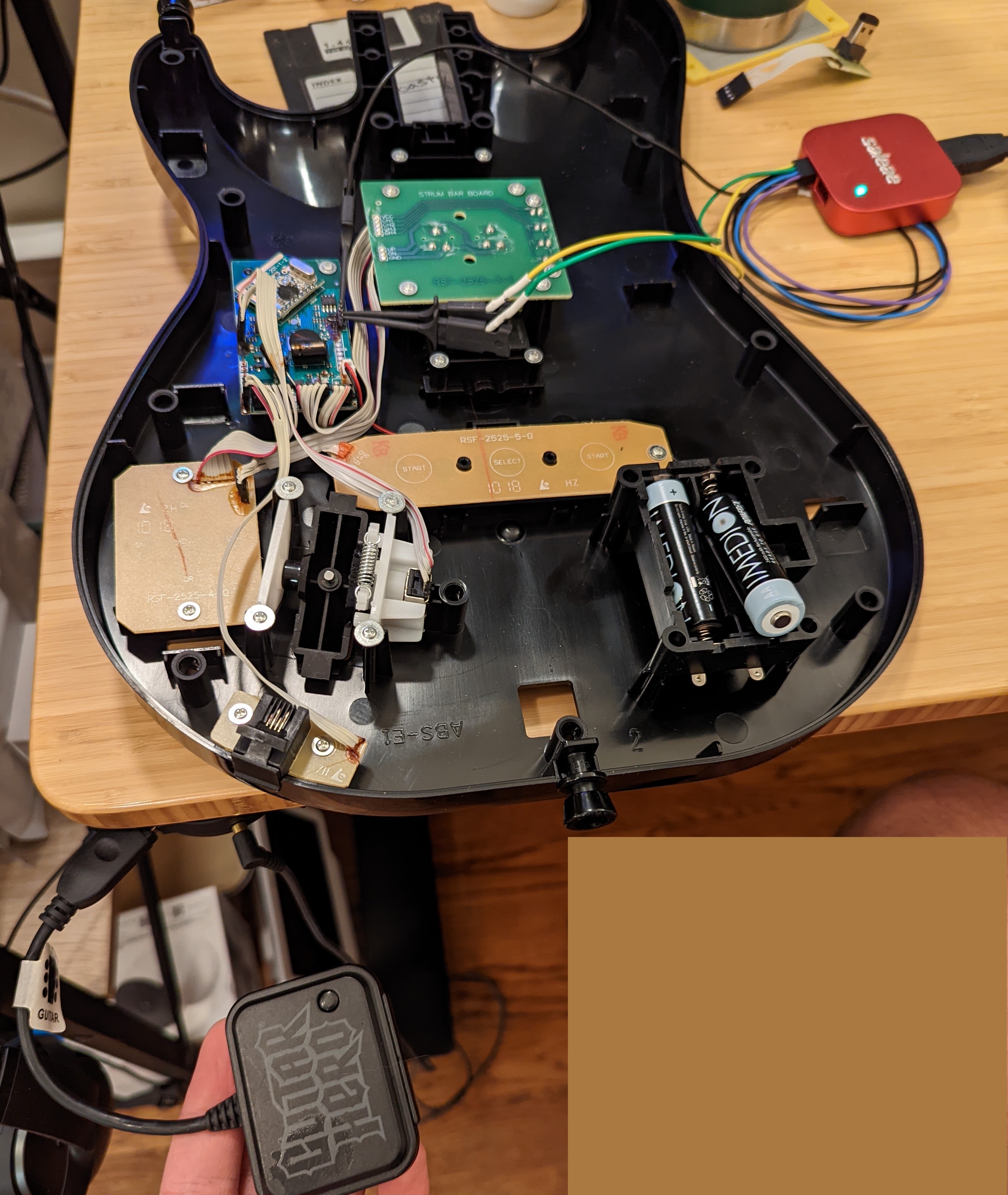
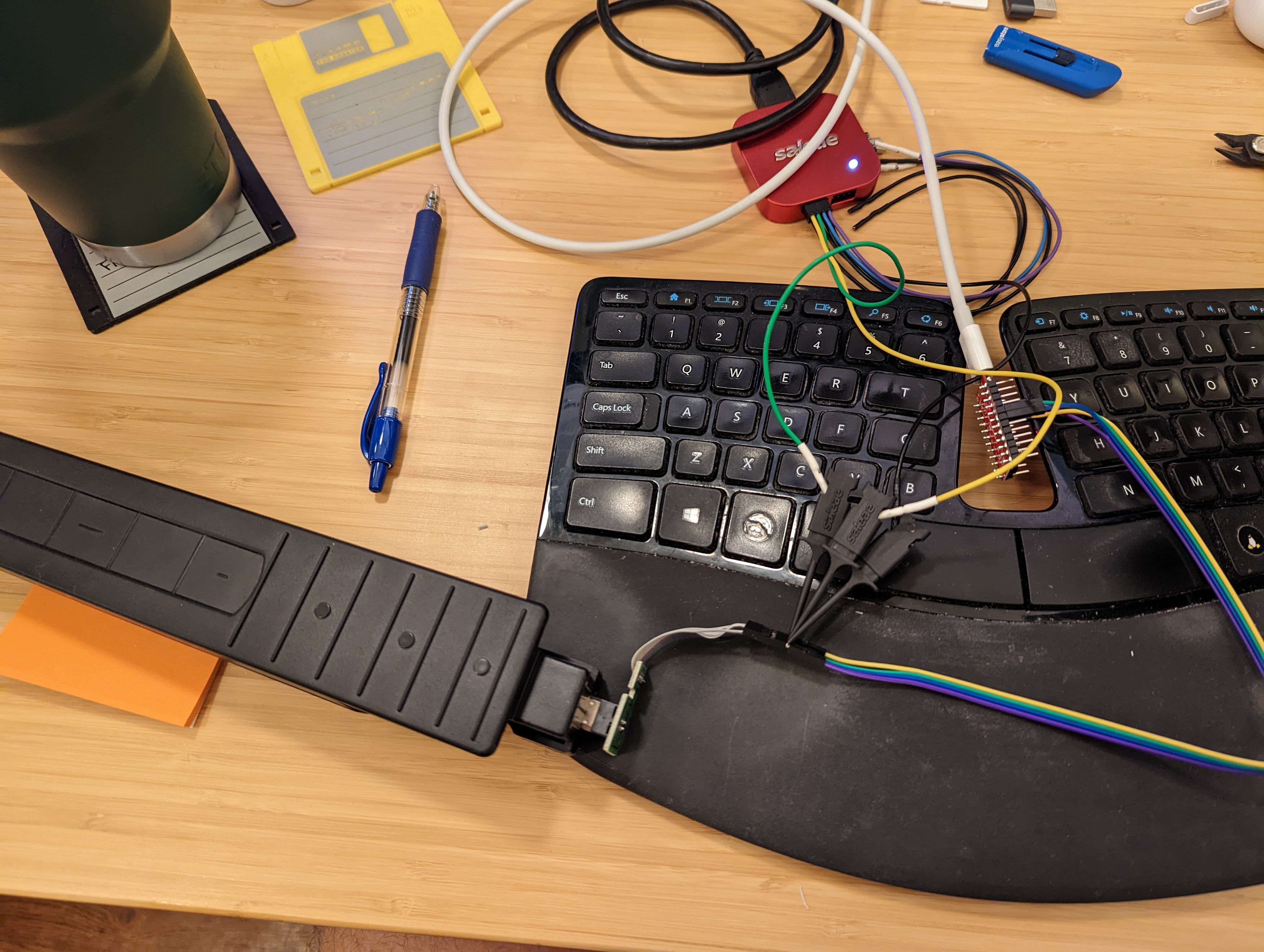
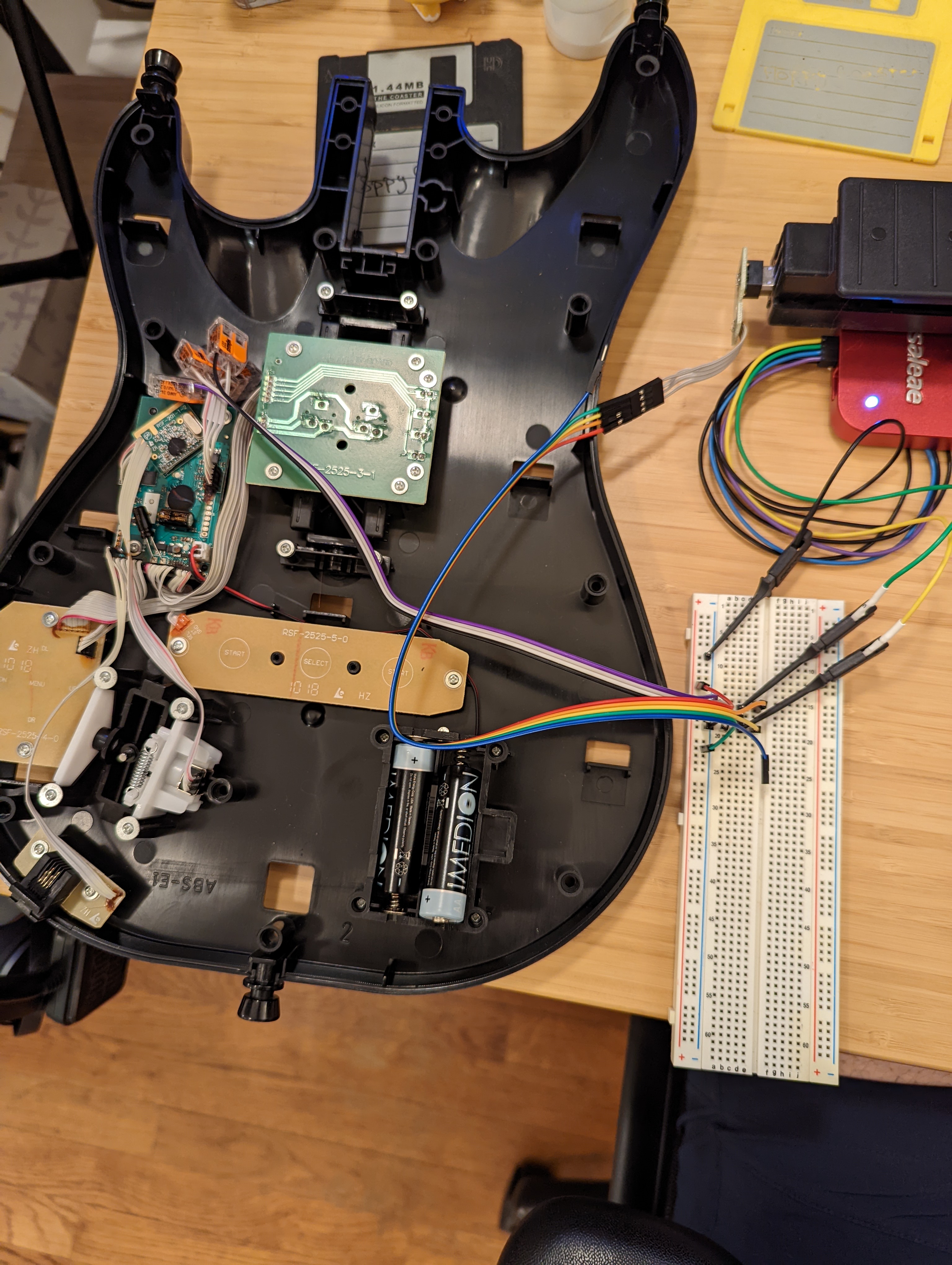
Ok, so I need to actually plug in the neck too. This is annoying because the internal guitar connection are 2mm DuPont connectors, rather than the standard 2.54mm. To keep the existing headers, we can use a Pitch Changer (also on Amazon)
I get the neck plugged in, and we’re off to the races
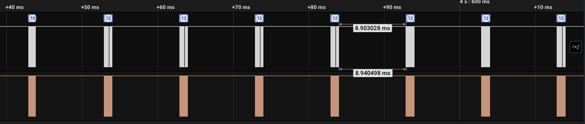
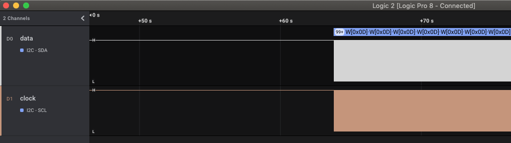
As we can see in the screen cap, there’s communication every 10ms. After clicking the buttons a few times, I find that the data is:
- one initial write with data 0x00
- a read (perhaps some data about the neck?)
- a repetition every 10ms:
- a write with data 0x10
- a read of 2 bytes, with one changing byte then 0x01. This is maybe a cycling counter of some sort?
- a read of 6 bytes. The first byte is bitmask representing which of the buttons is held. The remaining 5 bytes vary when touching the touchpad
The bitmask is [yellow, blue, red, green, n/a, n/a, n/a, orange].
I can’t see the pattern for the remaining 5 bytes, but at least they’re consistent….
Green pad: 0x95 0x94 0x10 0x04 0x15
Red pad:   0xCD 0xCC 0x08 0x0A 0x4D
Green+red: 0xB0 0xAF 0x18 0x06 0x30
Yellow pad:0x1A 0x1A 0x04 0x12 0x9A
2022-04-13
I write an Arduino sketch to communicate with the neck. For the 5 bytes that change with pad input, I can’t spot a pattern, so I manually go through each possible pattern and record the byte values in the program in a giant if/else. There’s only 31 possibilities (32 counting all-open), so it’s not too bad, and we actually only need to consider the first of those 5 bytes.
Next steps: transfer this to a Arduino Pro Mini, then finish the conversion in the guitar.
2022-04-14
I transferred the code to the Pro Mini and set it up for low power consumption. I’m powering the neck off a digital output pin, so that I can turn it off entirely during sleep. And I’m listening on an interrupt pin for signals to power up / down from the other microcontroller. After removing the power LED, the sleep current is only 0.7mA, pretty good! There’s definitely more gains to be eked out (e.g. like this blog post), but that’s good enough for tonight. Now to get it wired up!
The code I wrote communicates with the neck over I2C and activate a digital output when a neck button is pressed, to communicate with an Arduino running Sanjay900’s Ardwiino software.
The final layout looks like this:
Guitar neck <-> Arduino running my code <-> Arduino running sanjay900’s code